CREATOR Arduino module (CREATino)
CREATino allows the user to add custom Arduino libraries to their programs.
Warning
This library only works with the ESP32 gateway and the supported ESP32 boards. You must set up the gateway before using this module.
Using CREATino library functions
In the Editor view, go to Library → Load Arduino Library. The available functions will be displayed on the right.
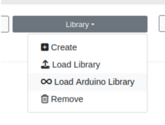
Library functions available after loading an Arduino library.
Tip
Except the printf function (which is excusive for Espressif Arduino devices) and rgbLedWrite (only used for built-in internal LEDS in ESP32-C6 and ESP32-H2) all the functions displayed can be found in Arduino's documentation and in Help → Creatino Help.
Creating your first program
As in the original Arduino sketches, CREATino programs must have a structure composed by a "setup" and a "loop" function. CREATOR provides an example template in Help → Examples → Example 1: Template for new examples.
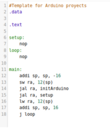
Example template for new CREATino programs.
Aspects to consider when using this library
- The supported ESP32 boards do not support have floating point operations. Arduino functions with
floatordoubleoutputs will fail. -
Avoid using the following GPIO pins:
-
GPIO8: BOOT MODE pin. It might show the following error:
Serial port /dev/ttyUSB0 Connecting...................................... A fatal error occurred: Failed to connect to ESP32-C3: Wrong boot mode detected (0x0)! The chip needs to be in download mode. For troubleshooting steps visit: [https://docs.espressif.com/projects/esptool/en/latest/troubleshooting.html](https://docs.espressif.com/projects/esptool/en/latest/troubleshooting.html) -
GPIO 18 and 19: Debug pins
-
CREATOR Arduino Debug page
CREATOR now supports a graphic simulator using CREATOR executor. It can be accessed next to the Statics Menu when loaded Arduino Library
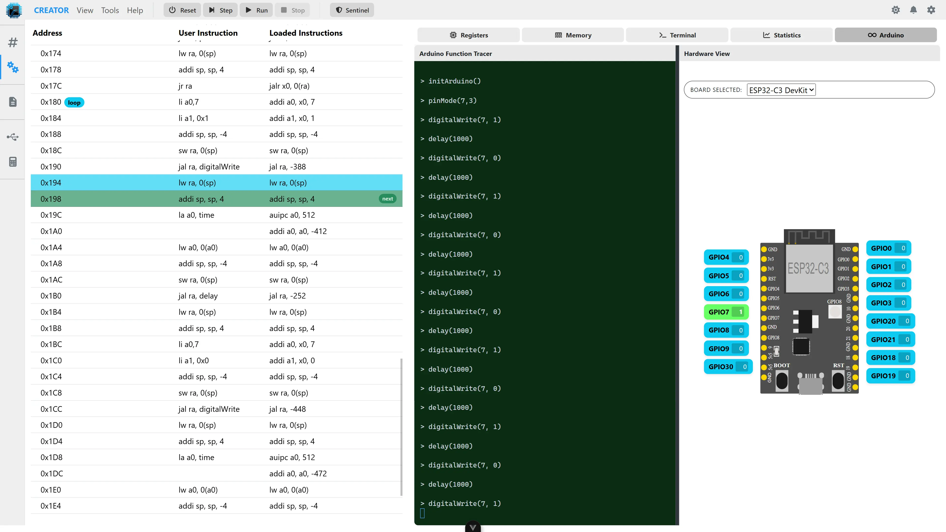
Arduino Debug page in the simulator.
Available boards
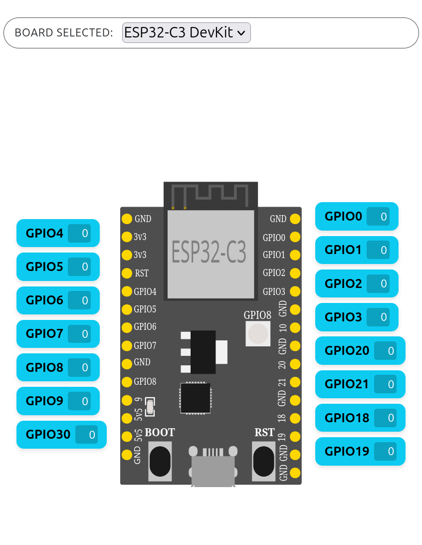
At the moment, the user can access to ESP32C3-DevkitC-02 and ESP32-C6-DevKitC-1 graphic models inside the simulator.
Note
"GPIO30" inside the ESP32C3 board refers to RGB-Inside Led.
| ESP32C3-DevKitC-02 | ESP32C6-DevKitC-1 |
|---|---|
 |
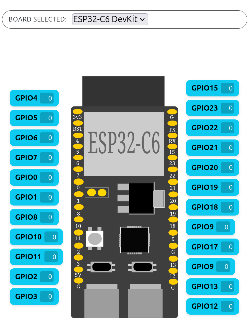 |
| 15 general-purpose pins. | 22 general-purpose pins. |
Debug panel
To help debugging and following the execution of Arduino functions, there is Arduino Function Tracer Terminal, which shows the user what action has been done (function execution, text, interrupts warning...)
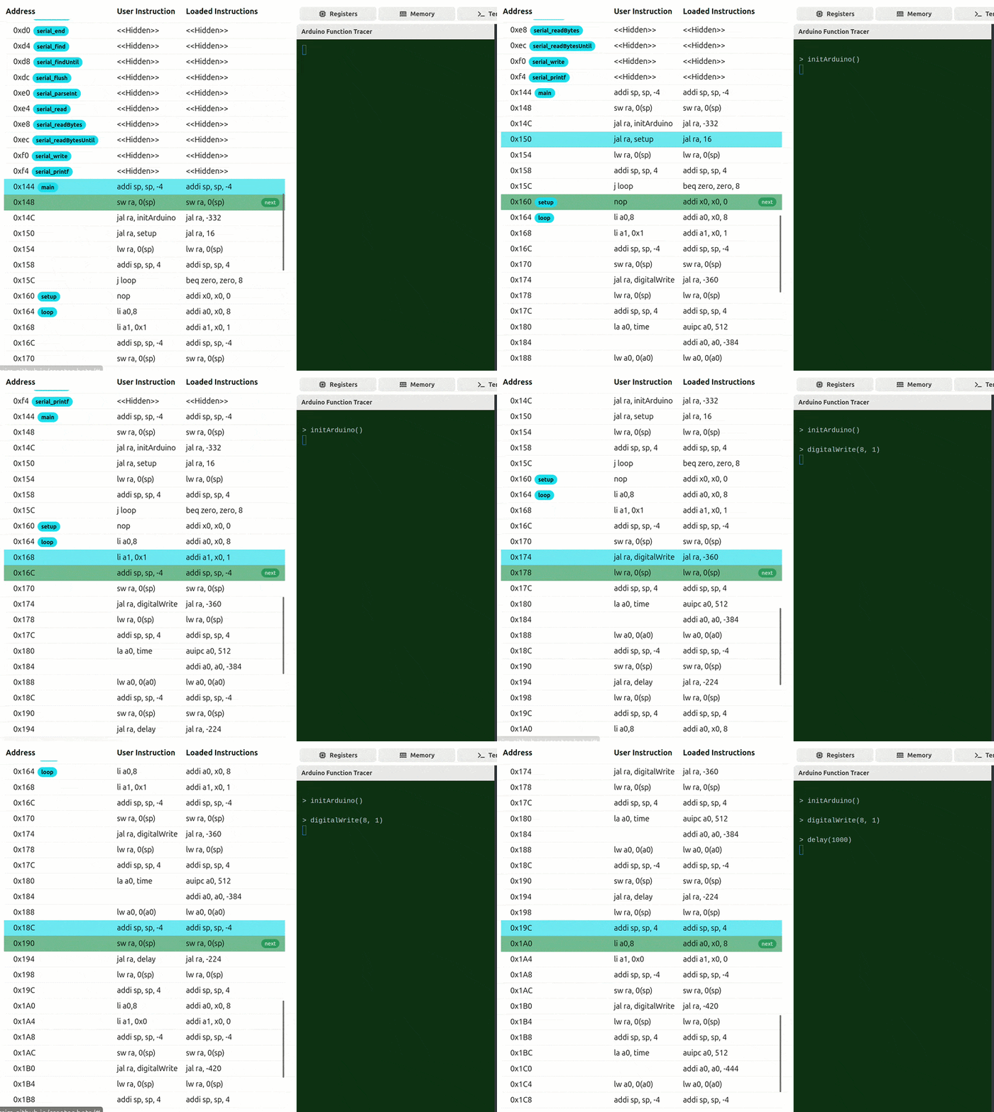
Arduino Function Tracer terminal during program execution.
Pin modes
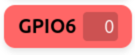
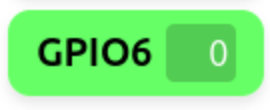
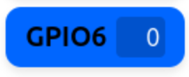
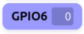
Inside the pin modes that can be assigned with the pinMode Arduino command, the pins can have different colors
| Input | Output | Input_Pullup | Input_Pulldown | Analog |
|---|---|---|---|---|
 |
 |
 |
 |
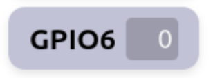 |
| Digital input mode. | Digital output mode. | Combines input configuration (0x01) with pull-up (0x04). |
Ensures the pin reads LOW when disconnected. | Configures the pin for analog input (ADC) |
Change values inside the pin
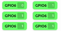
During the execution and debug of Arduino programs, the user can change manually the GPIO values to simulate peripherial interaction (a button presses, a ultrasound sensor value...). As all GPIO ESP32 pins are general-purpose, they can have whole numbers detected.
During the execution of a program, the user can see also how its value changes (e.g. lighting up a LED).
| Automatic Change | Manual Change |
|---|---|
 |
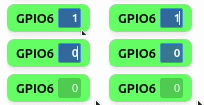 |
Changed value when used digitalWrite. |
Changed value manually. |
Interrupts
Arduino Module includes functions related to high-level interrupts attachment that can be reproduced graphically inside the simulator.
Tip
By default, interrupts are enabled. To disable them, use the Arduino function nointerrupts().
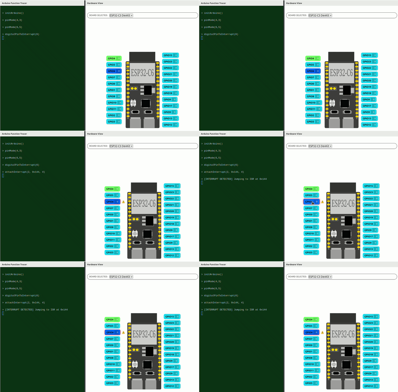
High level interrupt reproduced graphically in the simulator.
Example
See Example 14: High level interrupts example to try this feature
Examples
Example 1: Internal LED Blink
This example is used to check if GPIO functions work correctly inside a ESP32-C3 board.
Components:
- ESP32-C3-DevKitC-02 board
Step 1: Setup
In the ESP32-C3-DevKitC-02, the internal LED pin corresponds to pin 30, and it must be tagged as output. We use pinMode function for this.
The possible values for the mode are:
| Mode | Value | Usage |
|---|---|---|
INPUT |
0x01 |
Digital input mode |
OUTPUT |
0x03 |
Digital output mode |
INPUT_PULLUP |
0x05 |
Combines input configuration (0x01) with pull-up (0x04) |
INPUT_PULLDOWN |
0x09 |
Ensures the pin reads LOW when disconnected |
ANALOG |
0xC0 |
Configures the pin for analog input (ADC) |
In this case, our setup function will look like this:
setup:
  # pinMode(30, OUTPUT);
  li a0, 30
  li a1, 0x03
  addi sp, sp, -4
  sw ra, 0(sp)
  jal ra, pinMode
  lw ra, 0(sp)
  addi sp, sp, 4
  jr ra
Step 2: Loop
The LED has been set up; now it is we can try to make it turn on and off, creating a blinking effect. For this, we'll use the digitalWrite function.
This function needs the number of the pin used (pin 30) and the state to write (in this case 0x1 or HIGH to turn on the light and 0x0 to turn it off)
We will also use a delay function to generate a delay, in milliseconds, between changes of state of the LED. For this example, we'll store the length of the delay in memory.
The result is:
.data
  time:
    .word 1000

.text
loop:
  # digitalWrite(LED_BUILTIN, HIGH);
  li a0,30
  li a1, 0x1
  addi sp, sp, -4
  sw ra, 0(sp)
  jal ra, digitalWrite
  lw ra, 0(sp)
  addi sp, sp, 4

  # delay(time);
  la a0, time
  lw a0, 0(a0)
  addi sp, sp, -4
  sw ra, 0(sp)
  jal ra, delay
  lw ra, 0(sp)
  addi sp, sp, 4

  # turn off

  # digitalWrite(LED_BUILTIN, LOW);
  li a0,30
  li a1, 0x0
  addi sp, sp, -4
  sw ra, 0(sp)
  jal ra, digitalWrite
  lw ra, 0(sp)
  addi sp, sp, 4

  # delay(time);
  la a0, time
  lw a0, 0(a0)
  addi sp, sp, -4
  sw ra, 0(sp)
  jal ra, delay
  lw ra, 0(sp)
  addi sp, sp, 4
  j loop
Now the LED will start blinking.
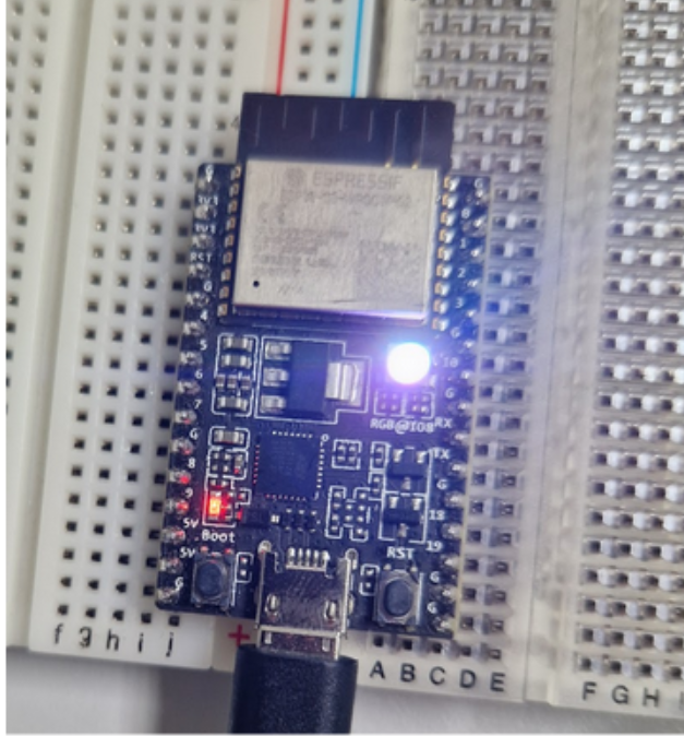
Internal LED blinking on the ESP32-C3-DevKitC-02 board.
Example 2: Button + LED
In this example we'll turn an LED on when the button is pressed.
Components:
- ESP32-C3-DevKitC-02 board
- Button (in GPIO 6)
- LED (in GPIO 4)
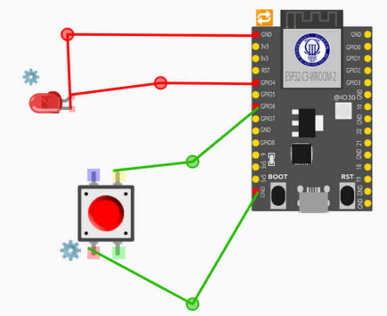
Button and LED circuit setup for Example 2.
There are two ways to do this: synchronously, using an infinite loop, and asynchronously, using interrupts.
Using an infinite loop
Step 1: Setup
First we'll establish the LED as an output and the button as input. As shown in Use example 1, you need to configure the pin mode with pinMode before using the pins:
.data
  buttonPin: .word 6
  ledpin:    .word 4

.text

setup:
  # pinMode(buttonPin, INPUT_PULLUP);
  la a0, buttonPin
  lw a0, 0(a0)
  li a1, 0x05  # INPUT_PULLUP
  addi sp, sp, -4
  sw ra, 0(sp)
  jal ra, pinMode
  lw ra, 0(sp)
  addi sp, sp, 4

  # pinMode(ledpin, OUTPUT);
  la a0, ledpin
  lw a0, 0(a0)
  li a1, 0x03  # OUTPUT
  addi sp, sp, -4
  sw ra, 0(sp)
  jal ra, pinMode
  lw ra, 0(sp)
  addi sp, sp, 4

  jr ra
Step 2: Reading the button
Once set up, we start the infinite loop by reading the button state using digitalRead, to which we only need to pass the button’s pin (in this case, pin 6).
In our case, if it detects that the button is pressed, the button_pressed function will be called. Otherwise, the LED will remain off. A small delay is added to avoid overloading the system:
.data
  time:  .word 100

.text
loop:
  la a0, buttonPin
  lw a0, 0(a0)
  addi sp, sp, -4
  sw ra, 0(sp)
  jal ra, digitalRead
  lw ra, 0(sp)
  addi sp, sp, 4

  mv t0,a0

  li t1 ,0 # LOW

  beq t0, t1, button_pressed

  la a0, ledpin
  lw a0, 0(a0)
  li a1, 0x0
  jal ra, digitalWrite

  la a0, time
  lw a0, 0(a0)
  addi sp, sp, -4
  sw ra, 0(sp)
  jal ra, delay
  lw ra, 0(sp)
  addi sp, sp, 4

  j loop
Step 3: Turning the LED on
As shown in Example 1, we will turn on the LED when button is pressed:
button_pressed:
  la a0, ledpin
  lw a0, 0(a0)
  li a1, 0x1
  addi sp, sp, -4
  sw ra, 0(sp)
  jal ra, digitalWrite
  lw ra, 0(sp)
  addi sp, 4

  la a0, time
  lw a0, 0(a0)
  addi sp, sp, -4
  sw ra, 0(sp)
  jal ra, delay
  lw ra, 0(sp)
  addi sp, 4

  jr ra
Using interrupts
Another way to achieve this project is by using GPIO interrupts, which are much more immediate but more complex to program.
In this case, we will use the attachInterrupt and digitalPinToInterrupt Arduino functions to obtain the interrupt number that can be assigned to the interrupt service routine for that pin.
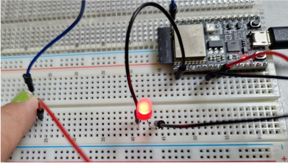
LED toggling through button interrupts.
Step 1: Setup
As shown in Example 1, you need to configure the pin mode with pinMode before using the pins.
Then we connect the button pin to an interrupt routine or ISR (which we will call blink) that runs automatically when the button is pressed. For this we will use attachInterrupt function.
The attachInterrupt function takes the following parameters:
- The interrupt position corresponding to the pin for which we want to detect the interrupt (we use
digitalPinToInterrupt(pin)) - The memory address where the interrupt service routine is located (in this case, we call it
blink) -
The interrupt mode, that can be one of the following:
Mode Value Usage DISABLED0x00Interrupt disabled RISING0x01Interrupt triggered on the rising edge (when the pin changes from LOW to HIGH) FALLING0x02Interrupt triggered on the falling edge (when the pin changes from HIGH to LOW) CHANGE0x03Interrupt triggered on any change of the pin state (both LOW→HIGH and HIGH→LOW) ONLOW0x04Interrupt triggered while the pin remains LOW ONHIGH0x05Interrupt triggered while the pin remains HIGH ONLOW_WE0x06Same as ONLOW, but with write enable — allows modifications or writing to related registers while the pin is LOWONHIGH_WE0x07Same as ONHIGH, but with write enable
In this case, as we want the interruption when the button is pressed, we choose the ON_LOW mode.
This is how the setup function will look:
.data
  ledPin:       .byte 4
  interruptpin: .byte 6
  state:        .byte 0  #LOW
  on_low:       .byte 0x04

.text
setup:
  # pinMode(ledPin, OUTPUT);
  la t1, ledPin
  lb a0, 0(t1)
  li a1, 0x03  # OUTPUT
  addi sp, sp, -4
  sw ra,0(sp)
  jal ra, pinMode
  lw ra,0(sp)
  addi sp, sp, 4

  # pinMode(ledPin, INPUT_PULLUP);
  la t1, interruptpin
  lb a0, 0(t1)
  li a1, 0x05  # INPUT_PULLUP
  addi sp, sp, -4
  sw ra,0(sp)
  jal ra, pinMode
  lw ra,0(sp)
  addi sp, sp, 4

  # digitalPinToInterrupt(interruptpin);
  la t1, interruptpin
  lb a0, 0(t1)
  addi sp, sp, -4
  sw ra,0(sp)
  jal ra, digitalPinToInterrupt
  lw ra,0(sp)
  addi sp, sp, 4


  # attachInterrupt(digitalPinToInterrupt(interruptPin), blink, ON_LOW);
  la a1, blink
  la t1, on_low
  lb a2, 0(t1)
  addi sp, sp, -4
  sw ra,0(sp)
  jal ra, attachInterrupt
  lw ra,0(sp)
  addi sp, sp, 4

  jr ra
Step 2: ISR definition.
We want to change the LED state when an interrupt is detected (the button's state changes). For that, we'll modify a variable stored in memory that indicates the LED’s state, as follows:
blink:
  addi sp, sp, -8
  sw ra, 4(sp)
  sw t0, 0(sp)

  la t0, state
  lb a0, 0(t0)
  xori a0, a0, 1  # 0->1, 1->0
  sb a0, 0(t0)
  lw t0, 0(sp)
  lw ra, 4(sp)
  addi sp, sp, 8
  jr ra
Step 3: Loop
The LED will be turned off until the button is pressed, as shown in the following code:
loop:

  # digitalWrite(ledPin, state);
  la t1, ledPin
  lb a0, 0(t1)
  li a1,0
  addi sp, sp, -4
  sw ra,0(sp)
  jal ra, digitalWrite
  lw ra,0(sp)
  addi sp, sp, 4

  # delay(100)
  li a0, 100
  addi sp, sp, -4
  sw ra,0(sp)
  jal ra, delay
  lw ra,0(sp)
  addi sp, sp, 4
  j loop

setup:

  # pinMode(ledPin, OUTPUT);
  la t1, ledPin
  lb a0, 0(t1)
  li a1, 0x03 #OUTPUT
  addi sp, sp, -4
  sw ra,0(sp)
  jal ra, pinMode
  lw ra,0(sp)
  addi sp, sp, 4

  # pinMode(ledPin, INPUT_PULLUP);
  la t1, interruptpin
  lb a0, 0(t1)
  li a1, 0x05  # INPUT_PULLUP
  addi sp, sp, -4
  sw ra,0(sp)
  jal ra, pinMode
  lw ra,0(sp)
  addi sp, sp, 4

  # digitalPinToInterrupt(interruptpin);
  la t1, interruptpin
  lb a0, 0(t1)
  addi sp, sp, -4
  sw ra,0(sp)
  jal ra, digitalPinToInterrupt
  lw ra,0(sp)
  addi sp, sp, 4

  # attachInterrupt(digitalPinToInterrupt(interruptPin), blink, CHANGE);
  la a1, blink
  la t1, change
  lb a2, 0(t1)
  addi sp, sp, -4
  sw ra,0(sp)
  jal ra, attachInterrupt
  lw ra,0(sp)
  addi sp, sp, 4

  jr ra
Example 3: Text input/output using serial output
For this use case, we are going to make a little use of basic functions from the Arduino Serial library. For more information, here is the official documentation (not all functions are available in this library, as they are not the most suitable for the environment in which we are working).
Warning
By definition, serial input functions are very fast (they do not wait for you to press Enter) and do not display a callback of what has been written. The purpose of this library is to familiarize yourself with these functions; therefore, it is the student's responsibility to monitor each step of what is being done.
Just as we previously used the ecall instruction to print messages in assembly CREATOR programs, here we will use the serial_printf function, which is part of Espressif's Arduino component.
Unlike higher-level functions like Serial.print and Serial.println, serial_printf requires explicit format specifiers to indicate the data types being printed; otherwise, the output is interpreted as a string.
On the other hand, we will use the serial_readBytes function to see how text input works. There is the serial_read variant (which only takes 1 character), serial_readBytesUntil (which stops storing characters when it finds the specified character), and those that parse, such as serial_parseInt (which only takes numbers).
Components:
- ESP32-C3-DevKitC-02 board
Step 1: Save messages to print in memory
For this use case we are going to declare in data section:
- The initial message to be displayed.
- The buffer allocated to store the input text.
- The message that includes a placeholder for outputting the entered text.
- An auxiliary callback used to display the entered number.
This would be reflected in the code as follows:
.data
  space:   .zero 100 #Buffer to place the string
  initial: .string "Introduce number of letters:\n"
  aux: .string "%d\nType your message\n"
  print:  .string "Your message: %s\n"
Step 2: Start terminal output and input.
On most boards, such as Arduino and Espressif, in order to use the terminal, it needs to be initialized with a specific frequency. In this case, we will use the serial_begin function with a baud rate of 115200.
If a value other than the one given is entered, strange characters may be printed or nothing may be printed at all.
It is declared in the code as follows:
setup:
  li a0,115200
  addi sp, sp, -4
  sw ra, 0(sp)
  jal ra, serial_begin
  lw ra, 0(sp)
  addi sp, sp,4
  jr ra
Step 3: Check if the terminal is correctly open.
A good practice that can be seen in Arduino is to use serial_available to see if the terminal has opened correctly.
If it has a value greater than 0, it means that it is operational and ready to use.
!!! note
For simplicity's sake, you will often find that this check is not performed... but using serial_available is a very good error control.
So, we start our loop as follows:
loop:
    addi sp, sp, -4
    sw ra, 0(sp)
    jal ra, serial_available
    lw ra, 0(sp)
    addi sp, sp, 4
    beqz a0,aux_print
    j loop
aux_print is an auxiliary function to indicate to the user that they should enter the number only once. This is purely aesthetic but can provide clarity to the user.
aux_print:
    #serialPrintf
    la a0,initial
    addi sp, sp, -4
    sw ra, 0(sp)
    jal ra, serial_printf
    lw ra, 0(sp)
    addi sp, 4
    j read_num
read_num reads a number from terminal. In this case, we use the serial_parseInt function to get a number per terminal.
Question
Why don't we use serial_read? Because serial_read, although it returns a number, interprets the input in ASCII code. ️
If we enter the number 4 via the terminal, the values change:
- In
serial_read: 52 - In
serial_parseInt: 4
Since serial_read is very fast, we will not move on to the next step if there is no number greater than 0 collected in a0, leaving the following code snippet:
read_num:
    addi sp, sp, -4
    sw ra, 0(sp)
    jal ra, serial_parseInt
    lw ra, 0(sp)
    addi sp, sp,4mv t0, a0
    bnez t0, print_int
    j read_num
A small auxiliary function called print_int was created to view the callback of the value specified as length, as follows.
print_int:
  la a0, aux
  mv a1,t0
  addi sp, sp, -4
  sw ra, 0(sp)
  jal ra, serial_printf
  lw ra, 0(sp)
  addi sp, 4
  j read_function
The read_function reads the text of the requested length. Once we have the length of our string, we collect the text we want to add with serial_readBytes, which is blocking until the requested length of characters has been reached.
We would end up with an implementation like this:
read_function:
  la a0, space
  mv a1, t0 # number of letters it will have
  addi sp, sp, -4
  sw ra, 0(sp)
  jal ra, serial_readBytes
  lw ra, 0(sp)
  addi sp, sp, 4
  bne t0, a0, read_function
  la a0, print
  la a1, space
  addi sp, sp, -4
  sw ra, 0(sp)
  jal ra, serial_printf
  lw ra, 0(sp)
  addi sp, 4
  jr ra
And this is the result!
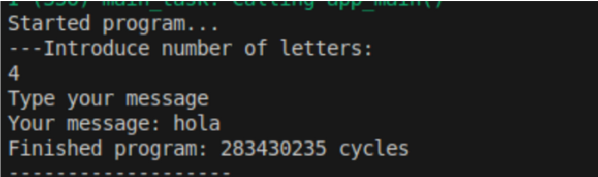
Text input and output using the serial terminal.
Example 4: Daytime running lights with analogRead
This time, we are going to make a small LED that lights up when it detects low light, using an LDR.
Warning
The sensitivity values of the sensor may vary depending on the location of the student and their device. We recommend having a flashlight or something that gives off light handy and using the debugger or prints.
Components:
- ESP32-C3-DevKitC-02 board
- LDR or photoresistor (in GPIO 2)
- LED (in GPIO 4)
- 10kΩ resistor
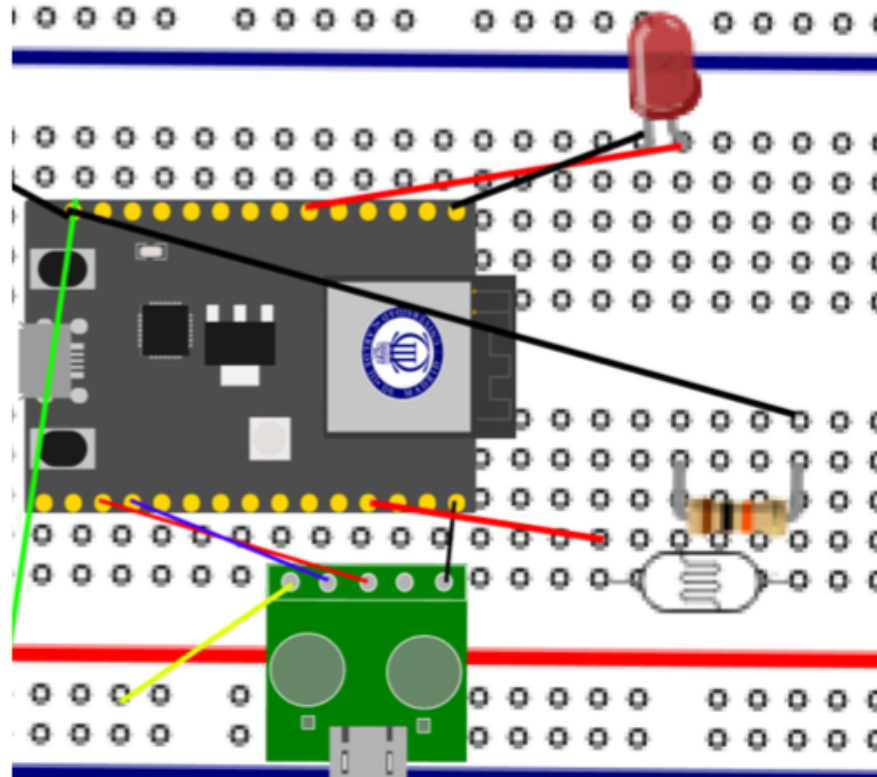
Circuit setup with the LDR sensor and LED.
To find resistors with the correct value, look at the color code on their bands. You can either look at the color guide, use this calculator, or simply look for a resistor that matches the one in the photo.
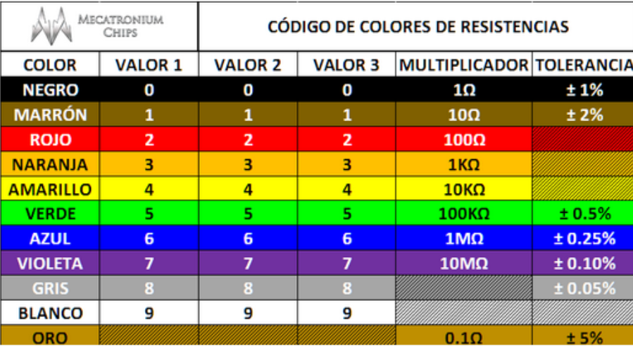
Resistor color code guide.
Step 1: Initialize LDR, pin, and serial output.
To use the sensor, we must initialize it with pinMode to the value of INPUT (0x01) as we saw in Figure 2.1.
The setup code would look like this:
.data
    lightSensorPin: .word 2
    ledPin: .word 4
    time: .word 100
    aux_msg: .string "LDR value: %d\n"

.text
setup:
  # Serial
  li a0,115200
  addi sp, sp, -4
  sw ra, 0(sp)
  jal ra, serial_begin
  lw ra, 0(sp)
  addi sp, sp,4

  # PinMode LED
  la t1, ledPin
  lw a0, 0(t1)
  li a1, 0x03 # OUTPUT
  addi sp, sp, -4
  sw ra,0(sp)
  jal ra, pinMode #pinMode(ledPin, OUTPUT);
  lw ra,0(sp)
  addi sp, sp, 4

  # Light sensor pin
  la t1, lightSensorPin
  lw a0, 0(t1)
  li a1, 0x01
  addi sp, sp, -4
  sw ra,0(sp)
  jal ra, pinMode# pinMode(lightSensorPin, INPUT);
  lw ra,0(sp)
  addi sp, sp, 4

  jr ra
Step 2: Analog sensor reading
Once everything is up and running, we read the light level in the room using analogRead.
In this tutorial, after a few tests, we found that the values reached were between 1100 and 1400. The darker it is, the higher the resistance value will be. Therefore, a threshold of 1200 is set.
- If the sensor reaches a value higher than 1200, the LED will turn on (
lightUp). - If, on the other hand, it does not reach that value, the LED remains off (
turnDown).
In both cases, we add a small delayso that the readings are not so fast.
We finish with this code:
  # delay
      la a0, time
  lw a0, 0(a0)
  addi sp, sp, -4
  sw ra, 0(sp)
  jal ra, delay
  lw ra, 0(sp)
  addi sp, sp, 4

  j loop

loop:
  # read LDR
  addi sp, sp, -4
  sw ra,0(sp)
  jal ra, analogRead #analogRead(lightSensorPin);
  lw ra,0(sp)
  addi sp, sp, 4

  # Print value
  mv t1, a0
  mv a1,a0
  la a0,aux_msg
  addi sp, sp, -4
  sw ra, 0(sp)
  jal ra, serial_printf
  lw ra, 0(sp)
  addi sp, sp, 4

  # turn up led
  li t0, 1200 #Minumun value
  bgt t1, t0, lightUp
  blt t1, t0, turnDown

  j loop
And this is the result:
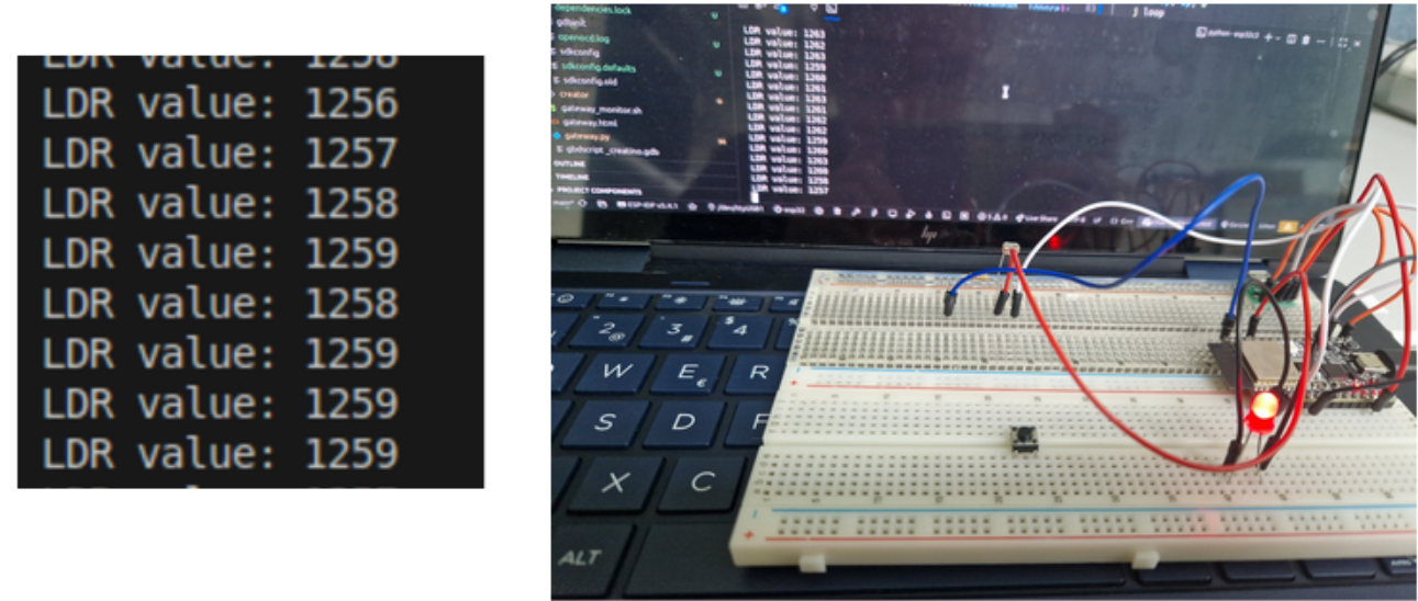
LED lighting up when low light is detected.
Example 5: Piano (Advanced)
This case is a little more complex than the rest, but very creative. It is recommended to have a breadboard with plenty of space.
Each musical note is a frequency that blows air into the buzzer membrane. Consult this page to learn how to calculate the other possible notes according to the desired tempo.
In this case, we are going to do it with interruptions. This example may cause a little more lag because there are continuous memory accesses and the “tone” function launches tasks.
Polling could be used.
Components::
- ESP32-C3-DevKitC-02 board
- 4 buttons
- A passive buzzer
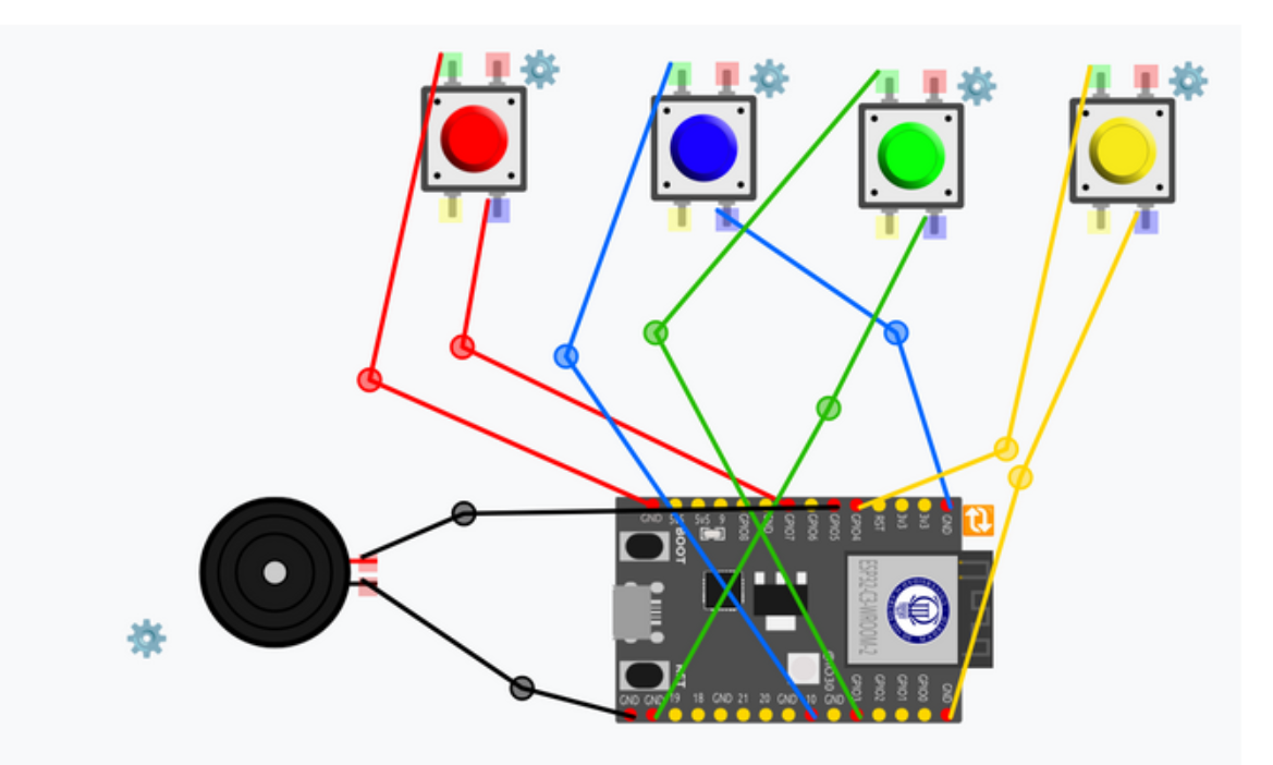
Breadboard setup with four buttons and a passive buzzer.
Step 1: Declaration of pins and values of musical notes
We indicate in the data the pins we are going to use (avoiding "dangerous" pins such as GPIO8 and GPIO1) and the frequency values of the musical notes.
Care must be taken with the position of these values, as we are going to use these memory positions as arrays.
In this example, we have positioned them as follows:
.data
  # GPIO
  buzzerPin: .word 5
  button_C4: .word 7
  button_D4: .word 10
  button_E4: .word 3
  button_G4: .word 4

  # Notes
  note_C4: .word 262
  note_D4: .word 294
  note_E4: .word 330
  note_G4: .word 392
  #aux
  button_count: .word 4
  time_delay: .word 10
  anyPressed: .word -1
  .align 4
  button_handlers:
      .word handleButton0
      .word handleButton1
      .word handleButton2
      .word handleButton3
Another way to position them is like this:
.data
  # GPIO
  buzzerPin: .word 5
  buttons:   .word 7,10,3,4

  # Notes
  notes:     .word 262,294,330,392

  # aux
  button_count: .word  4
  anyPressed:   .byte -1

.align 4
  button_handlers:
  .word handleButton0
  .word handleButton1
  .word handleButton2
  .word handleButton3
Step 2: Configuring all pins
In this case, we are going to complicate things a little, as there are a lot of pins to configure. First, we will configure pin 5 of the buzzer, which, unlike the buttons, will use an OUTPUT mode (since it emits a sound to the outside).
setup:
  # buzzer
  la a0, buzzerPin
  lw a0, 0(a0)
  li a1,  0x03 #OUTPUT
  addi sp, sp, -4
  sw ra, 0(sp)
  jal ra, pinMode
  lw ra, 0(sp)
  addi sp, sp, 4
Then, to configure the rest of the buttons, we created a loop that goes through all the selected buttons.
First, in setup, after initializing the buzzer, we initialize the variables in our loop:
  la  s0, button_C4  # Button list
  li  s1, 0  # Position in the list
  la  t3, button_count
  lw  s2, 0(t3)  # List length
Next, we move on to the loop_buttons function, where we will:
- Check if we have already gone through the entire list
- If this is not the case, we scroll through the data to find the pin number we want.
- Once the position has been obtained, we configure the button with
INPUT_PULLUPmode, as they are buttons. - As we indicated in the statement, we are going to use interrupts, so we have to assign them now knowing which button we are on (that is, we take advantage of the fact that the order of
button_handlersis the same as the order followed by the button array). For more information on how to assign interrupts, see example 2. We will indicate what the ISRs are like in the next point:# Attach Interrupts # Transform digitalPin into interrupt # digitalPinToInterrupt(interruptpin); mv a0, s4 addi sp, sp, -4 sw ra,0(sp) jal ra, digitalPinToInterrupt # Search the correct pointer lw ra,0(sp) addi sp, sp, 4 la t0, button_handlers add t1, t0, s3 lw a1, 0(t1) # Let the interrupt jump when button is pressed (on_low) # attachInterrupt(digitalPinToInterrupt(buttonPin[i]), handler[i], ON_LOW); li a2, 0x03 addi sp, sp, -4 sw ra,0(sp) jal ra, attachInterrupt lw ra,0(sp) addi sp, sp, 4 - We add up a position and re-enter the loop
- If we have finished going through the list, we return to main by executing a ret (or a
jr ra).
Step 3: Loop
This step can be done in two ways: with polling (i.e., constantly checking the status of all buttons) or with interrupts (pressing the button triggers an interrupt). The easiest way to do this exercise is to assign an interrupt to each button and, when pressed, have each one have its own ISR. Therefore, before starting the loop, we will create each of the necessary ISRs and assign them to the buttons. Refer to case 2 using interrupts for a better understanding.
In this case, we use a "flag" change since the tone() function underneath launches "tasks" or "processes" underneath, which is not safe to do in an ISR.
# ISR
handleButton0:
  la t0, anyPressed
  lw t1, 0(t0)
  li t2, 0  # assign button
  sw t2, 0(t0)
  jr ra

handleButton1:
  la t0, anyPressed
  lw t1, 0(t0)
  li t2, 1  # assign button
  sw t2, 0(t0)
  jr ra

handleButton2:
  la t0, anyPressed
  lw t1, 0(t0)
  li t2, 2  # assign button
  sw t2, 0(t0)
  jr ra

handleButton3:
  la t0, anyPressed
  lw t1, 0(t0)
  li t2, 3  # assign button
  sw t2, 0(t0)
  jr ra
Then, inside the loop, we check the status of the anyPressed flag and add a small delay so that the watchdog does not trip.
This loop checks that, if the flag is not at -1, the tone corresponding to that position sounds.
loop:
  la t0, anyPressed
  lw s0,0(t0)
  li t1, -1
  bne s0, t1, startTune

  # delay(200);
  la t0, time_delay
  lw a0, 0(t0)
  addi sp, sp, -4
  sw ra,0(sp)
  jal ra, delay
  lw ra,0(sp)
  addi sp, sp, 4

  j loop
Step 4: Playing the tune
In this case, once we have the position of the button that has been pressed, we search the memory array for the corresponding note value, similar to when we searched for the button.
To prevent the tone from having an indefinite duration, we have set a timeout of 200. Once the tone is played, it returns to the loop.
startTune:
  # Clean value
  la t0, anyPressed
  li t1, -1
  sw t1, 0(t0)

  # Search value
  la t0, note_C4
  slli s1, s0, 2
  add t1,s1,t0
  lw s2, 0(t1)  # note value

  # Play tone
  la t0, buzzerPin
  lw a0, 0(t0)
  mv a1,s2
  li a2, 200

  # tone(buzzerPin, notes[i], duration);
  addi sp, sp, -4
  sw ra,0(sp)
  jal ra, tone
  lw ra,0(sp)
  addi sp, sp, 4

  j loop
And there we have our piano:
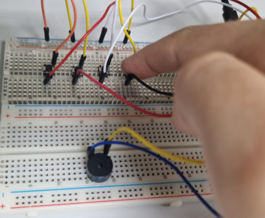
Finished piano playing musical notes with a buzzer.